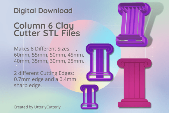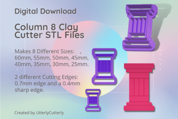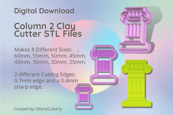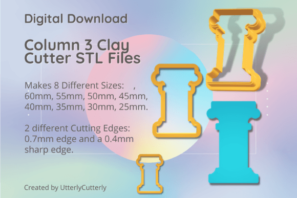
Column 1 Clay Cutter - Ancient Greek Rom: A Practical Guide to STL Files and Sizing
The Column 1 Clay Cutter - Ancient Greek Rom digital collection offers a sophisticated way to bring classical architectural details into modern polymer clay jewelry, ceramic work, and even culinary arts. As an STL file bundle designed specifically for 3D printing, this pack provides creators with immediate access to versatile tools without waiting for shipping. However, transitioning from purchasing a physical cutter to downloading and printing your own requires a shift in mindset. Many makers overlook critical technical specifications or misinterpret sizing conventions, leading to wasted filament, fragile tools, or designs that do not align with their creative vision.
Understanding the nuances of this specific digital download ensures you produce functional, high-quality cutters rather than decorative failures. This guide addresses common oversights regarding edge selection, dimensional accuracy, and material compatibility to help you get the best results from your Ancient Greek Roman column designs.
Selecting the Correct Cutting Edge for Your Material
One of the most frequent mistakes when using multi-option STL bundles is defaulting to a single blade type for every project. This pack includes two distinct cutting edge profiles, and choosing the wrong one can compromise both the tool's longevity and the finish of your work.
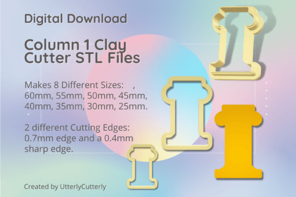
- Standard Edge (0.7mm wall): Features a 0.7mm wall thickness, a 3mm thick base, and a 12mm height. This is your workhorse for general shaping and softer clays.
- Sharp Edge (SE): Abbreviated as SE in the file names, this version has a 1mm support wall but a refined 0.4mm cutting edge. It shares the same 3mm base and 12mm height dimensions.
Using the Sharp Edge (SE) variant on dense, leather-hard ceramics or stiff polymer clay often leads to blade deformation because the 0.4mm tip lacks the necessary structural mass for heavy resistance. Conversely, using the standard 0.7mm edge for delicate jewelry components can result in excessive clay displacement and rough edges that require significant post-processing cleanup. Always match the edge profile to the density of your medium and the level of detail required. Reserve the SE files for soft conditioning clays and fine detailing, while relying on the standard 0.7mm wall for structural outlines and firmer materials.
Navigating Size Measurements and Scaling Errors
Digital files eliminate manufacturing variances, but they introduce interpretation errors. A widespread misunderstanding involves how cutter size is defined. For the Column 1 Clay Cutter - Ancient Greek Rom series, the stated size is measured from the longest ends of the design, not the width of the column shaft itself.
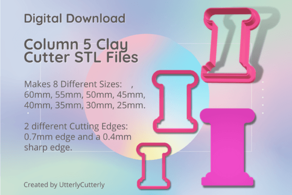
This distinction matters significantly when planning layout or matching sets. If you select a 60mm cutter expecting a 60mm wide column, you may find the actual usable impression area is smaller due to the vertical extent of the capital or base details. The available sizes—60mm, 55mm, 50mm, 45mm, 40mm, 35mm, 30mm, and 25mm—refer to this maximum bounding dimension.
To avoid sizing mismatches:
- Import the STL into your slicer software before printing.
- Use the digital caliper tool within the slicer to verify the exact X, Y, and Z dimensions.
- Print a single test cutter at your intended scale to confirm the "longest end" measurement aligns with your project requirements.
Assuming the filename number equals the functional working width is a shortcut that frequently results in ill-fitting jewelry components or cookie decorations that exceed intended boundaries.
Embossing Depth and Clay Thickness Compatibility
Ancient Greek and Roman column designs rely heavily on fluting and surface texture to achieve their aesthetic. In this STL pack, any embossing lines are set to a height of 10.5mm. This specification is non-negotiable and dictates your minimum material thickness.
If you attempt to use these cutters on clay sheets thinner than 1.5mm, the embossing features will likely punch through or create stress fractures during demolding. The 10.5mm relief depth requires sufficient material volume to capture the detail without structural failure. Beginners often roll clay too thin in an effort to save material or reduce baking time, only to discover the cutter renders the piece unusable.
For optimal results with these column designs, condition your clay to a consistent thickness of at least 2mm to 3mm. This provides adequate buffer for the 10.5mm embossing depth and ensures clean release. If you prefer working with thinner slabs, consider using only the outline function of the cutter and applying texture separately, rather than forcing a deep-relief tool onto incompatible stock.
Optimizing Print Settings for Functional Tools
Having access to professionally tested STL files does not guarantee success if your printer settings ignore the tool’s geometry. These cutters feature a 3mm thick base and 12mm total height, proportions designed for rigidity and grip. Printing with insufficient perimeters or low infill to save time undermines this engineering.
A 3mm base requires adequate top and bottom layers to prevent flexing during use. We recommend a minimum of four perimeter walls and 40% infill for both the standard and SE variants. The sharp edge version, despite its finer tip, still depends on the 1mm support wall and robust base for stability. Printing the SE file with standard vase mode or single-wall settings will produce a cutter that bends upon first contact with clay.
Additionally, ensure your bed adhesion is calibrated for the small footprint of the 25mm and 30mm sizes. Smaller cutters have less surface area contacting the build plate, making them prone to detachment mid-print. Using a brim or adjusting first-layer flow rate can prevent these losses without altering the functional dimensions of the cutter itself.
Managing Digital Assets and Future Expansion
Because this is a digital download and not a physical item, organization becomes part of the product experience. After payment, you receive immediate access to the files, but failing to establish a logical storage system leads to duplicate prints and version confusion. Create dedicated folders separated by edge type (Standard vs. SE) and size. Since new STL files are added to the store weekly, maintaining clear naming conventions prevents older versions from mixing with updated designs.
Furthermore, remember that these cutters are designed to integrate with other STL files in the ecosystem. When curating custom combos, verify that companion pieces share compatible scaling logic. Mixing column cutters measured by longest-end dimensions with shape cutters measured by diameter can create visual inconsistency in finished collections. Cross-reference measurements in your slicer before committing to multi-piece projects.
All cutters in this bundle undergo testing before sale, but your local environment—filament type, nozzle wear, ambient temperature—affects final output. Treat the provided specifications as a validated starting point, not an absolute guarantee. By respecting the relationship between edge geometry, material thickness, and print parameters, you transform a simple digital file into a reliable production tool capable of delivering consistent, professional-grade results across jewelry, ceramics, and culinary applications.